Summary
The overall objective of this lab is to sucessfully connect two ToF sensors and get measurements from both sensors simultaneously. Two Time-of-Flight sensors (VL53L1X) were given to measure the distances from objects.
Prelab
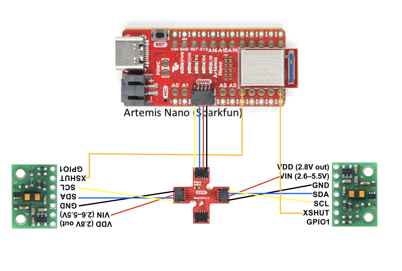
Before setting up codes to use the sensor, I first had to figure out the approximate location of the sensor and permanently solder the connection between the Qwiic port and sensors. I consulted with the lab TAs as well as classmates for most efficient placements, and finalized the wiring connection as shown below.

I decided to solder the sensors with the long QWIIC cables to maximize the mobility of the sensor location, and I am currently planning to put one sensor at the front of the robot and another at the side. In that case, I would potentially miss the obstacles in the back and the ones on the other side. The image below depicts the two sensors soldered and connected to the QWIIC breakout board.

The problem of using two sensors simultaneously is that the I2C sensor address is the same for the two sensors. Two ways to solve the issue is to change one of the sensor's address in the beginning or use the XSHUT pin to turn one off to use another and alternate each time. Due to efficiency I chose to change the sensor address for one of the sensors in the setup code of the Artemis.
I2C Channel sensor address
Through compiling Apollo3's Example05_Wire_I2C.ino file, the Artemis detected the sensor with address 0x29. According to the datasheet, the pre-set address is 0x52, but the address is bit shifted, and the last bit (0) is used for read write status.

Three modes of ToF Sensors
There are three modes of ToF sensors available: short, medium and long. According to the sensor's datasheet, the range of the sensor with varying lighting environment is as follows:


Although the long mode has much longer maximum distance measurment, it is fairly sensitive to ambient light. Thus, I concluded that short-distance mode is the right choice for this robot since it requires accuracy to be its top priority for accurate mapping or surroundings.
Testing Short distance mode
To test the sensors in short distance mode, I used the ReadDistance example code from the sensor library and altered a bit to investigate the reliability of the sensor as well as the ranging time for each sensor. Since the sensor is default set to long distance mode, I had to add distanceSensor.setDistanceModeShort(); to the setup code. Then, I gathered the distance data from 50 mm to the limit, which is 1300 mm. When the sensor exceeds the maximum, the measurment dropped to a low value (~300 to 400 mm). The graph below compares the ideal sensor with the actual sensor. It can be seen that the actual sensor starts to deviate slightly from the ideal sensor graph as the distance increases, meaning that the accuracy decreases the sensor gets further away from the wall.

Thus, it can be concluded that the sensor's range is indeed around 1300mm, but it is better practice to not go near the extreme since the value did get unstable as it reached the maximum. The accuracy is pretty good when the measurment is < 100 mm, but starts to decrease as it gets further away. In terms of repeatability, the measurement at same distance were pretty consistent especially at lower range values. The ranging time for the sensor was around 56 ms and was consistent regardless of the measurment distance.
Using two ToF Sensors
Aforementioned in the Prelab section, one of the two sensors either needs to shut down for the other one to be used or have its address changed in the beginning of code. Since it is inefficient to shut down and turn on each sensor every measurment, I decided to change one of the sensor's address. I connected one of the sensor's XSHUT pin with pin 8 in the Artemis and reset the address to 0x32 instead of the default 0x52 by turning off one of the sensors and setting the address through setI2CAddress().

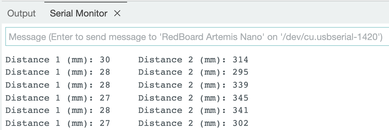
Then the two sensors are each defined under distanceSensor1 and distanceSensor2, so simultaneous measurements are possible. The following picture shows the simultaneous distance measurments, and the video attached also shows that the two sensors are measuring distance independently.

ToF sensor speed
To measure the time it takes to measure the distance using the sensors, I got the initial time at the start of the loop and final time at the end of the loop and subtracted the two values to get the total time for one loop in the same code for getting the two sensor values. The code used and the output are attached below, and it turns out that it takes exactly 108 milliseconds to execute one loop. The main limiting factor of the run time is the internal delay that the sensor has. For the sensor speed measurements, I addded an additional print statement to the two sensor output code used above, so that it prints the time whenever the sensor is not ready to output the value.

Time v. Distance
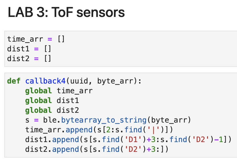
For the graphing task, I used the lab 2 GET_TEMP_5s_RAPID as my base code and added the necessary setup code onto the ble_arduino.ino. I created a new command called GET_DIST that gets the sensor outputs and sends it back to the computer in 'T:(time)|D1:(distance1)|D2:(distance2)' format.

The notification handler in the jupyter notebook then got the string and stored it separately in time_arr, dist1 and dist2 list variables.

Then, they were plotted as shown below.
