!DISCLAIMER!
At the end of the lab, I was looking through the values in the time array, and realized that my time scale was wrong. Please note that all time values for this lab is supposed to be 10 times bigger. :)
Summary
This objective of this lab was to set the IMU sensor to collect data from its accelerometer and gyroscope and get real-time roll, pitch and yaw information. Also, we equipped the Artemis, TOF sensors and IMU onto the robot, all powered through the given batteries.
We started off with setting up the IMU with the Artemis and analyzed its accelerometer and gyroscope data. Then, similar to the TOF sensor lab, we stored and sent the data through bluetooth, and finally, we connected all the sensors and batteries, and collected data from the RC car.
Setting up the IMU
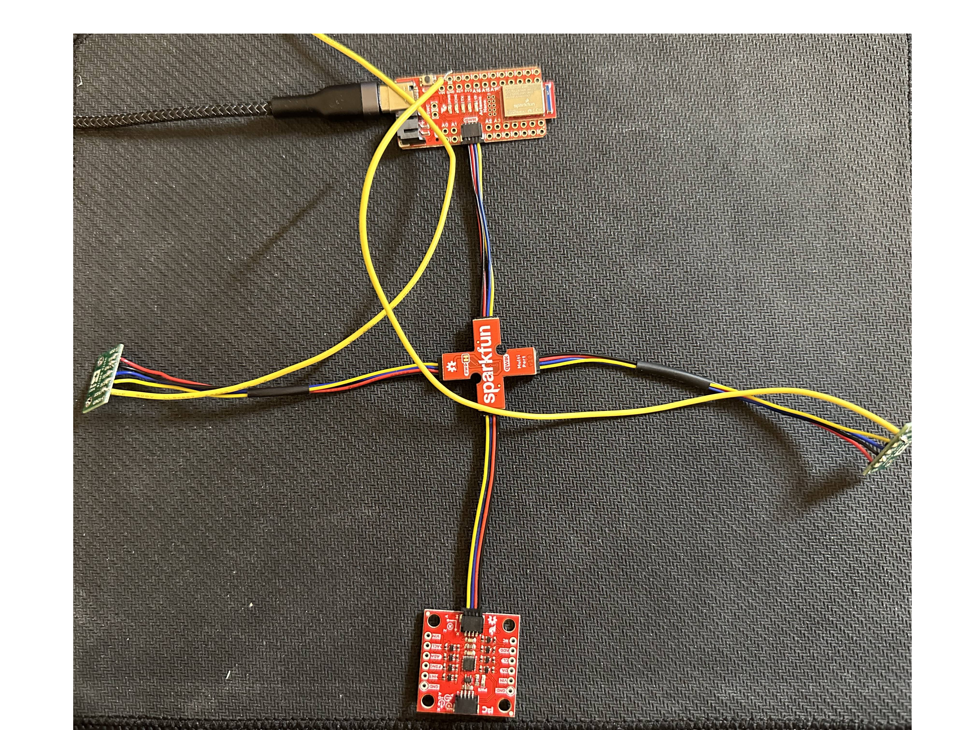
As shown in the image below, the IMU is connected to the Artemis, along with the two TOF sensors, through the QWIIC connectors.
To check the connection, we ran the example code from the IMU library, and the Serial Monitor showed the data from the accelerometer, gyroscope, magnetometer and the temperature sensor. In the example code, AD0_VAL represents the last bit of the IMU's I2C sensor. The default value is 0 because the ADR jumper is currently closed.
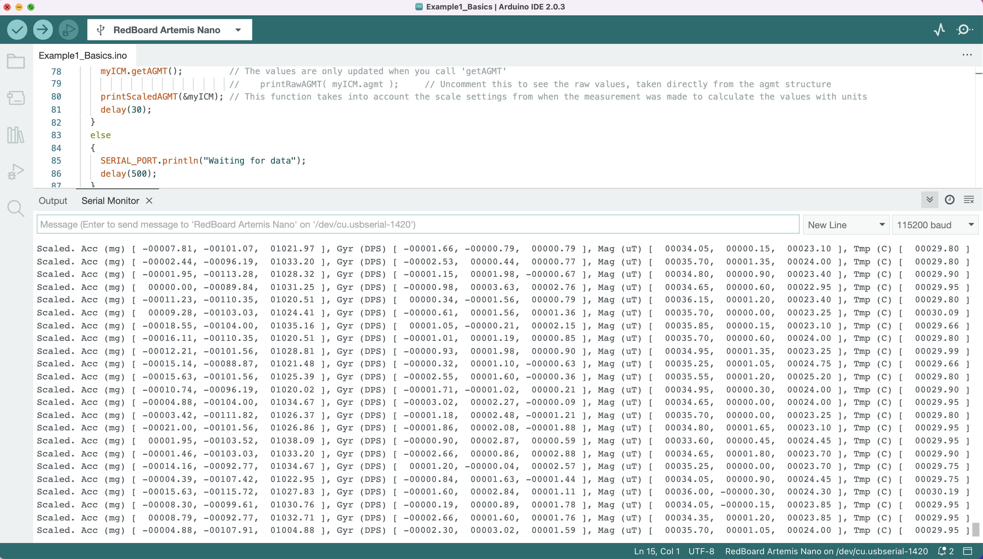
When the sensor is lying flat, the x and y accelerometer data are 0 while the z acceleration is the gravitational acceleration (~1000mg).
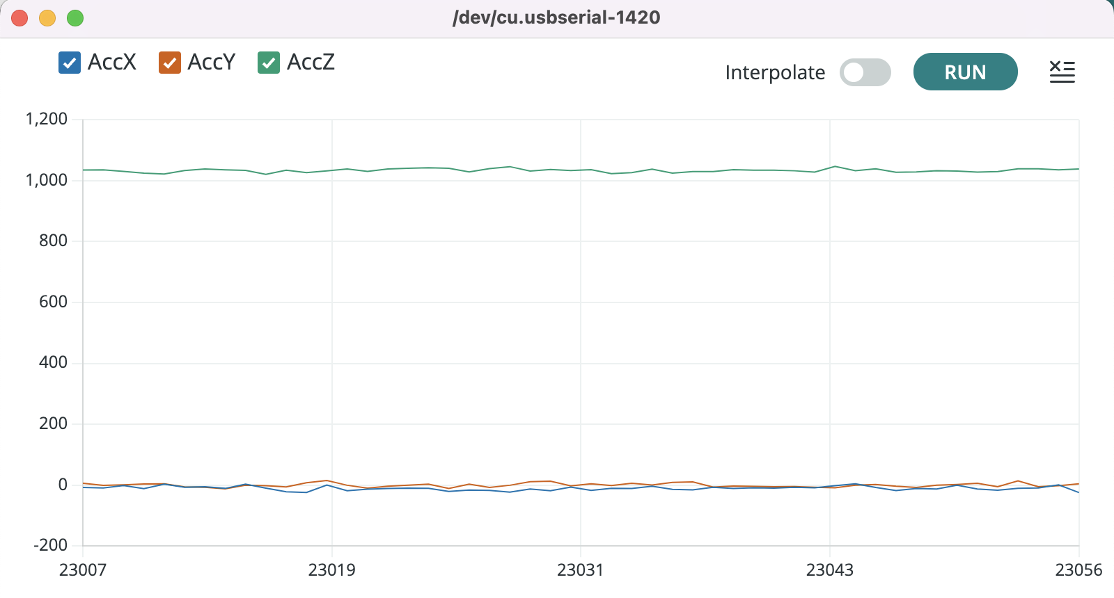
Accelerometer
With the accelerometer data, we can only calculate the pitch and roll values using the equations from lecture.


By implementing the equations onto the Artemis, we got the pitch and roll values from the IMU and plotted the data through the Serial Plotter. The following images depict the roll and pitch calculations at {-90, 0, 90} degrees.
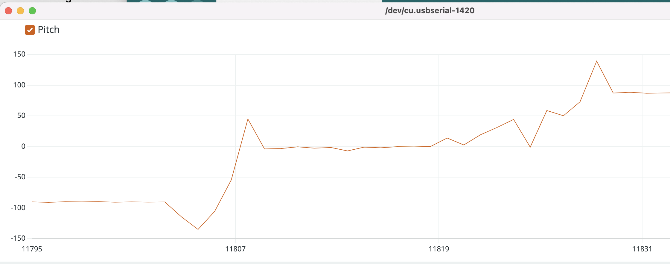
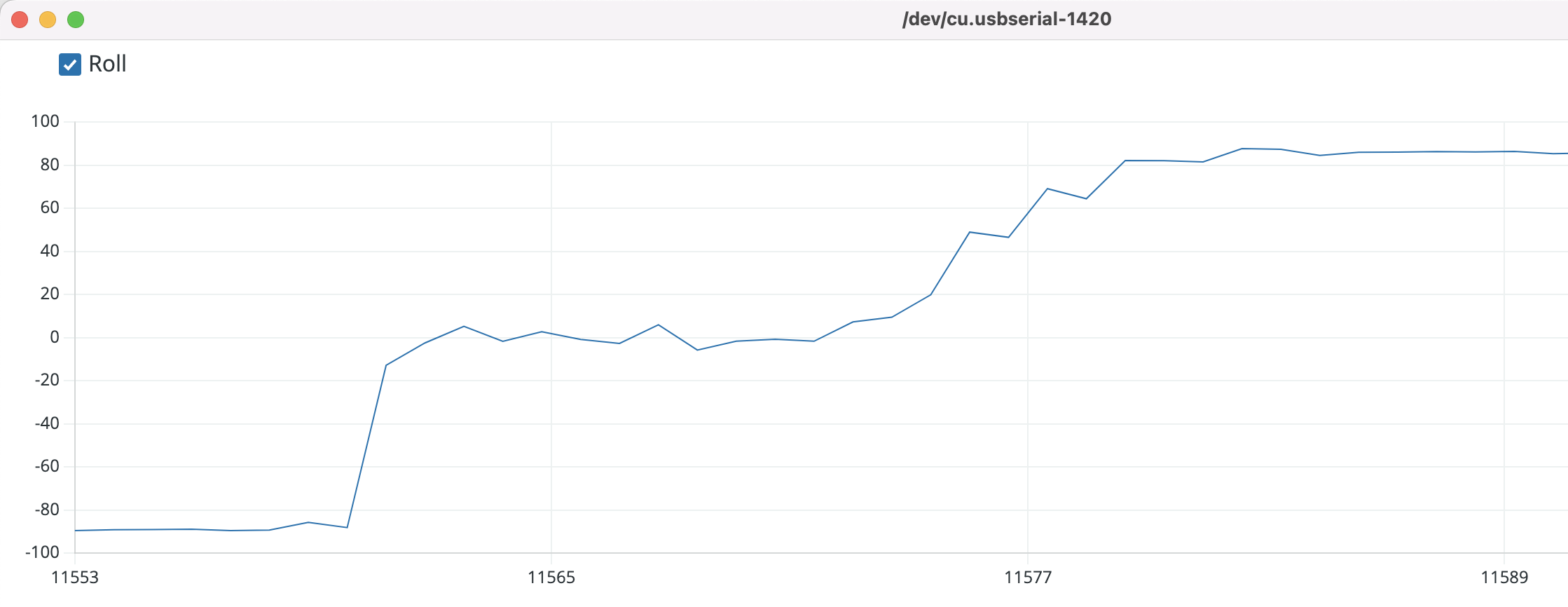
Due to the noisy nature of the accelerometer reading in the IMU, we used the Fourier Transform to analyze the noise in the frequency spectrum. We gathered 5 seconds worth of accelerometer's roll and pitch data and plotted them over time as well as their frequency domain signal. The resulting graphs are shown below.
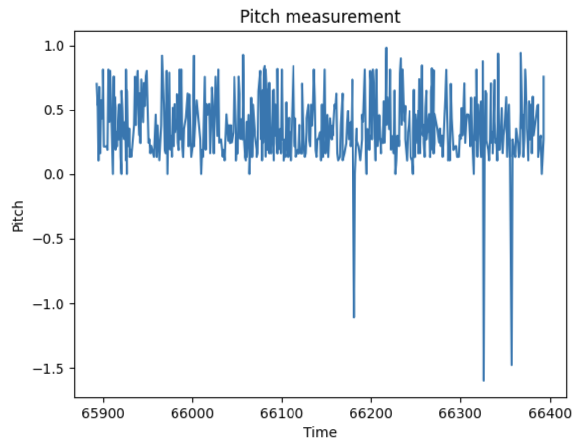
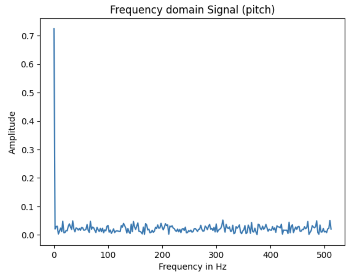
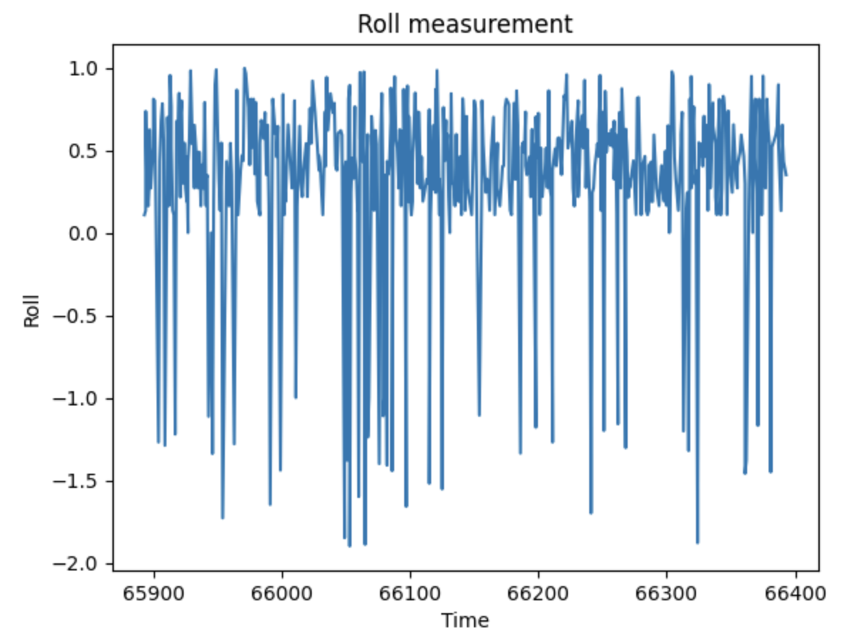
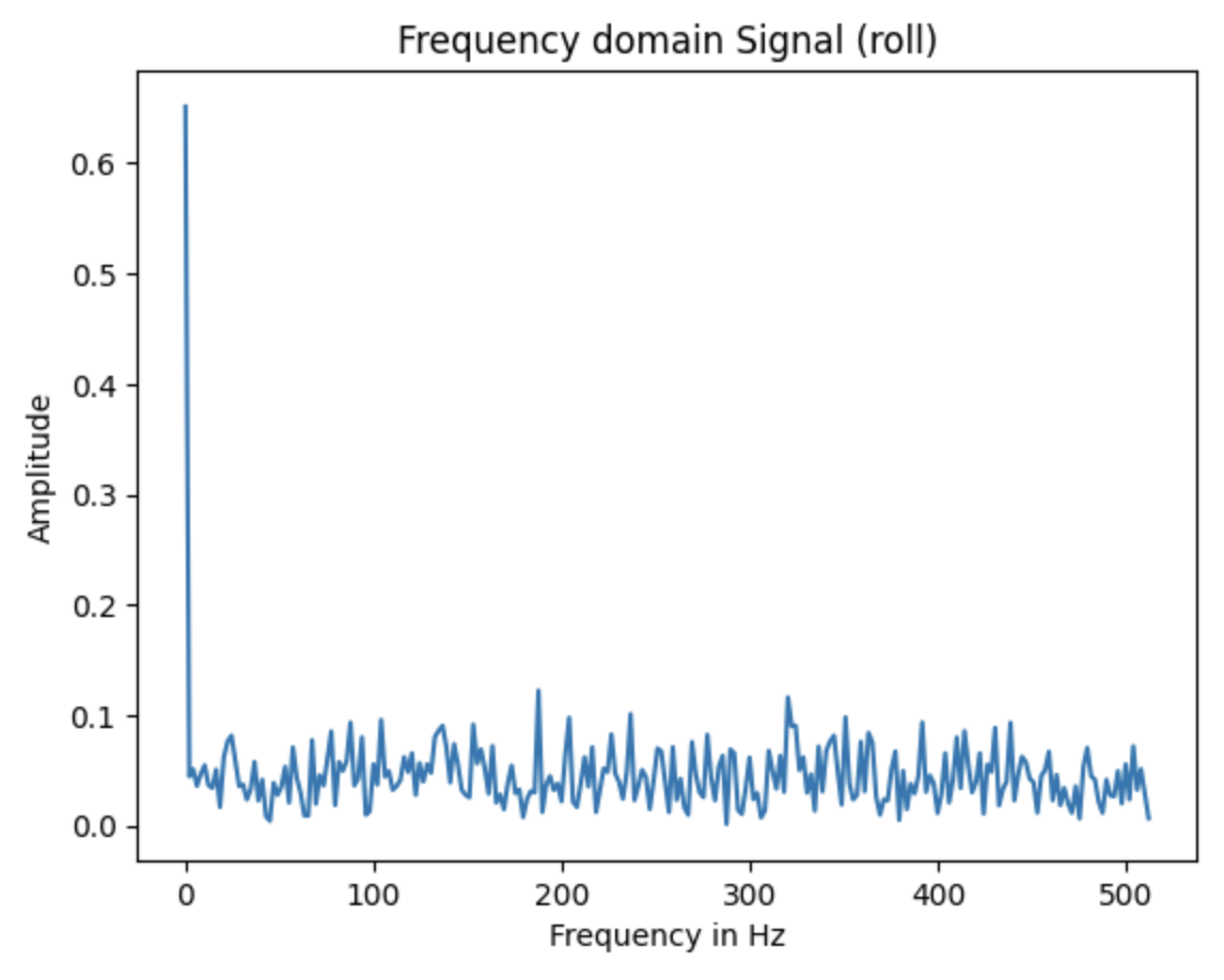
As one can see, there aren't that much noise in the IMU accelerometer data, since the frequency is mostly under 0.1 Hz, which I believe is due to the low pass filter that is already implemented. Thus, I do not need to implement an additional low pass filter.
Gyroscope
With the gyroscope, pitch, roll and yaw values can be calculated using the following equations from lecture.


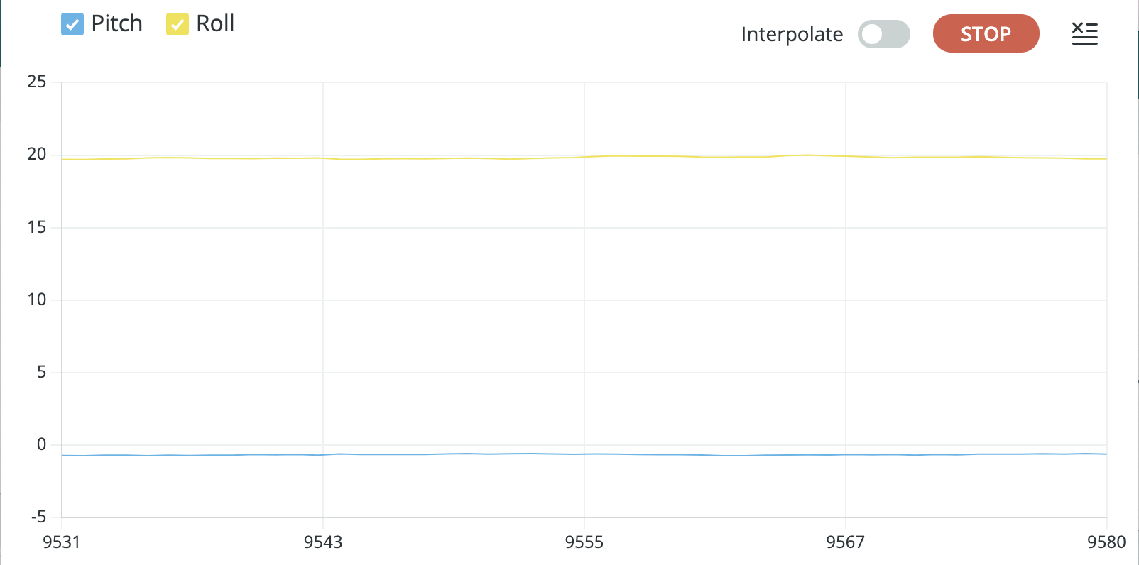
When compared with the accelerometer data, the gyroscope was more prone to errors when exposed to drift and quick vibrations. Furthermore, the range of the IMU is +/- 90 degrees for pitch and roll (as seen in data below), so we opted for a complimentary filter to ensure stable and accurate pitch and roll measurements. The final equations are shown below. I used 90% of the gyroscope data and 10% of the accelerometer data to find the complementary pitch/roll values.


Sample Data
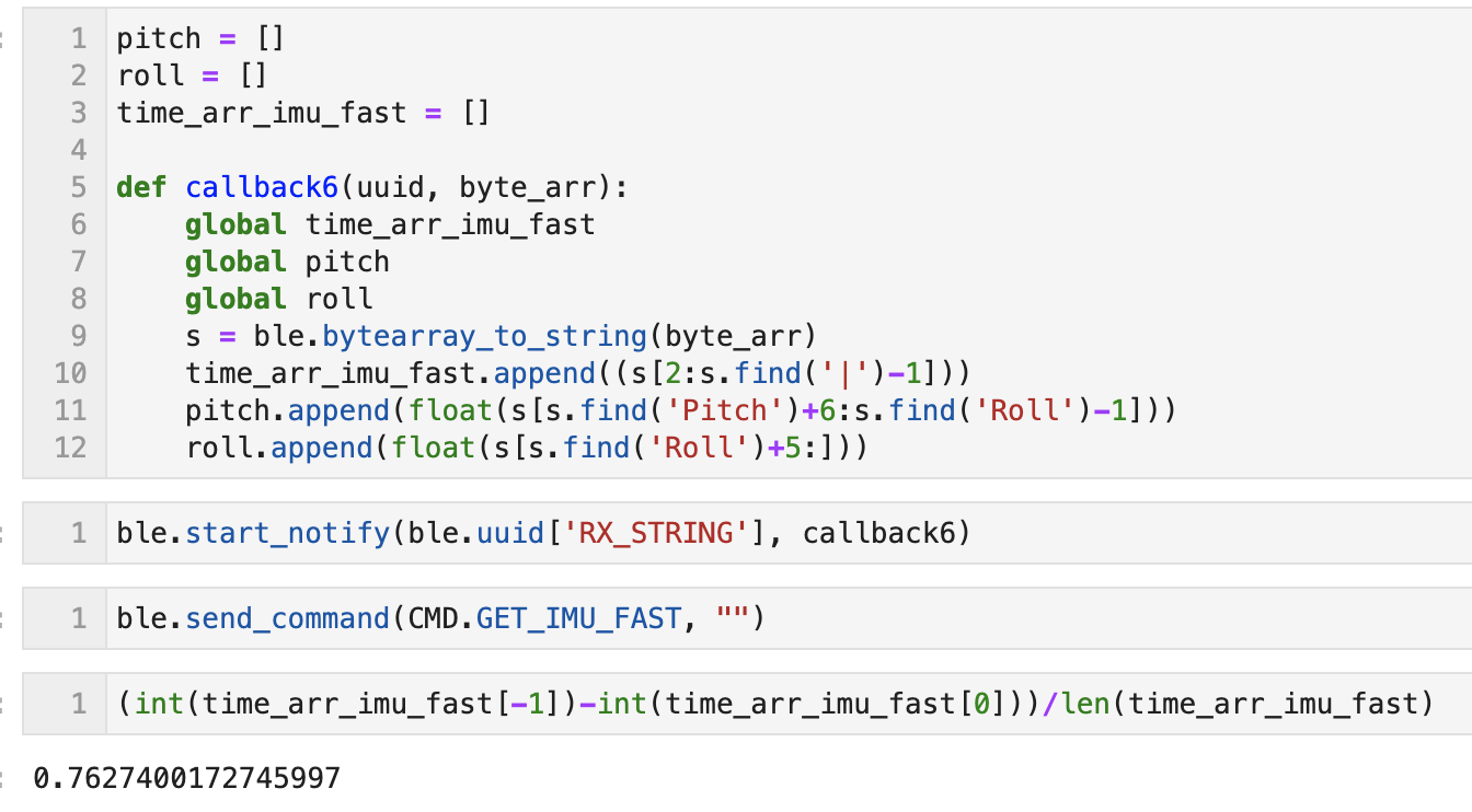
First, we gathered the IMU data as fast as we can by removing all the print statements and sending the data whenever it is ready. Once the data is received via bluetooth, python used the notification handler to collect data real time, and we calculated the time it takes to gather one set of IMU data, which was around 7.6 milliseconds. (In the image it says 0.76 ms as explained in the disclaimer at the beginning of the lab)
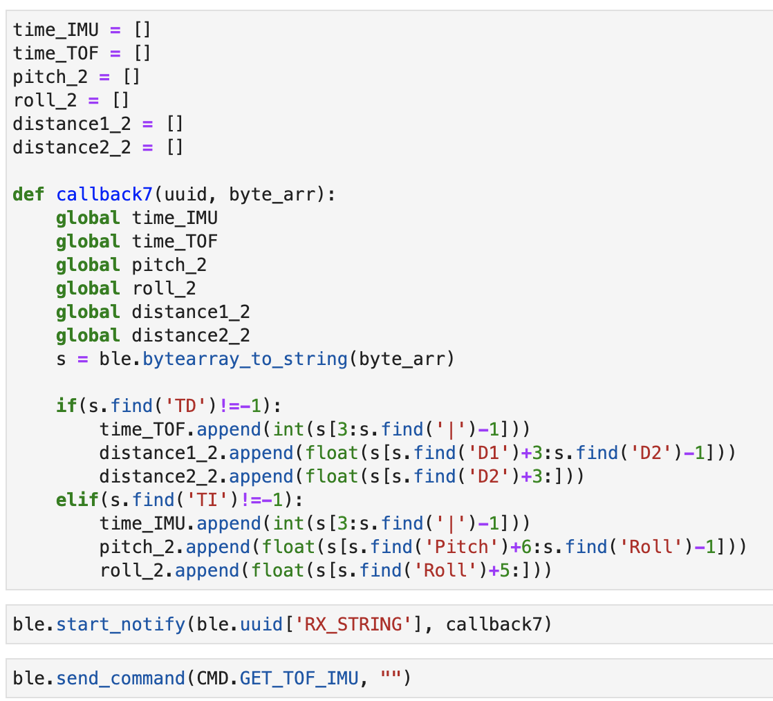
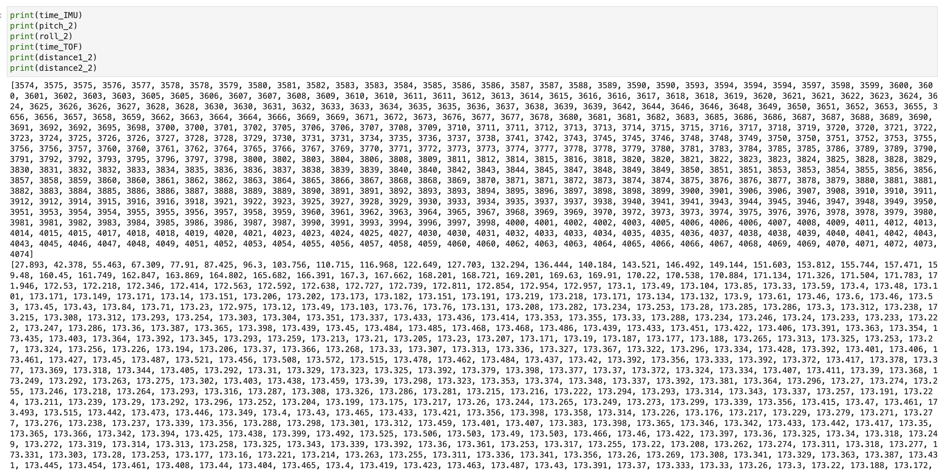
We integrated the code from lab 2 and 3, such that the Artemis captured both ToF and IMU sensor measurements through bluetooth connection. For ease of processing, I sent the data in two separate strings, one for each sensor. Then, once the data arrived, we organized the data into separate arrays for IMU time, pitch, roll, ToF time and the two distance sensors' readings. Due to faster data collection time for IMU, the array size for IMU data was large compared to that of the ToF sensors.
Cutting the cord
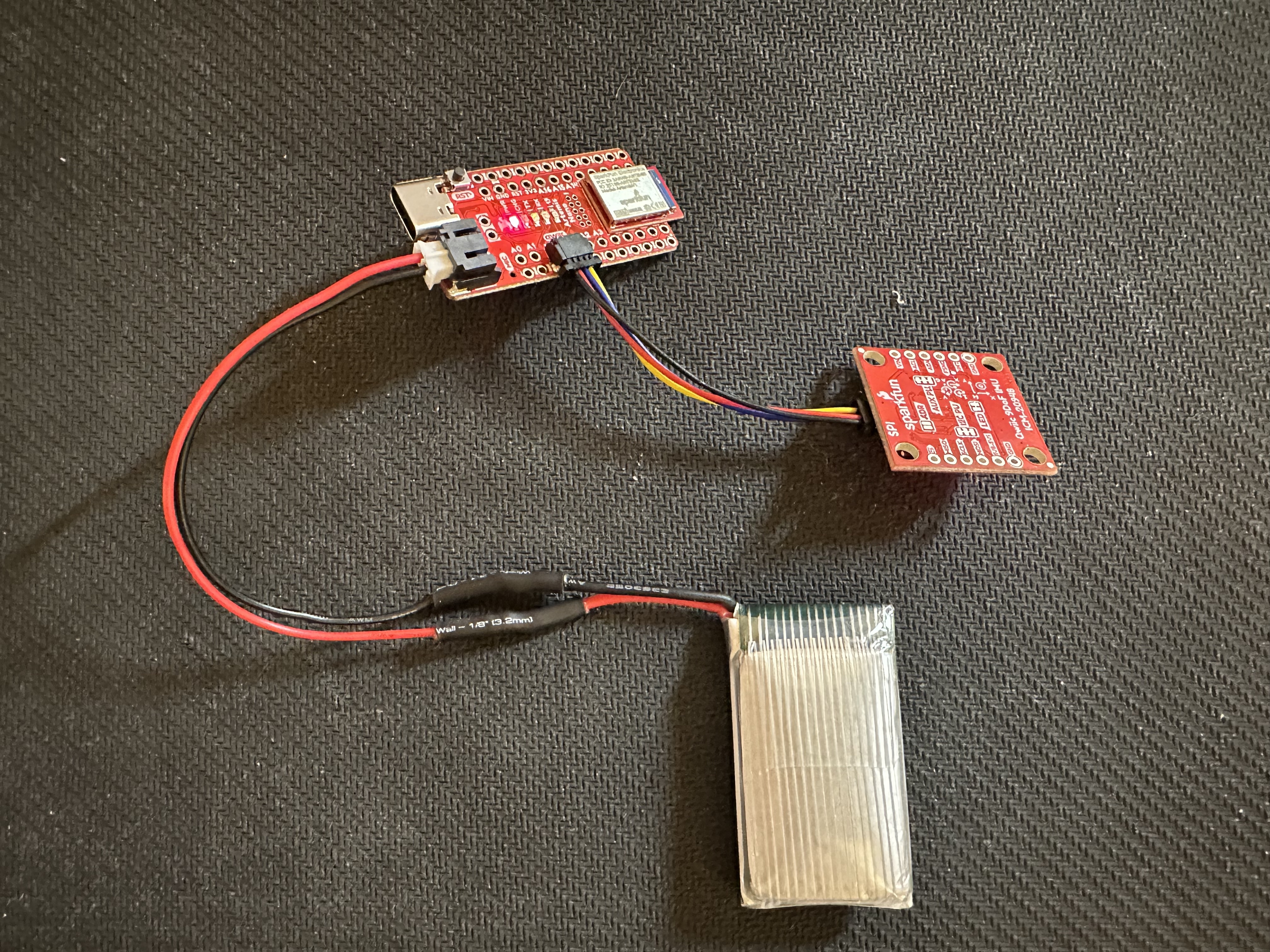
To connect the battery to the Artemis, I cut the battery wires one at a time, soldered them onto the JST connector, and covered the connection with the heat shrink. The 650 mAh battery was used for the Artemis since the larger capacity battery was saved for motor battery power.
Stunt!
After mounting the 850 mAh battery onto the RC car, we played around with the car and found that it is very sensitive to inputs and hard to control. Rapid reverse in direction caused the car to flip and constant rotation input caused the car to spin at relatively constant position.
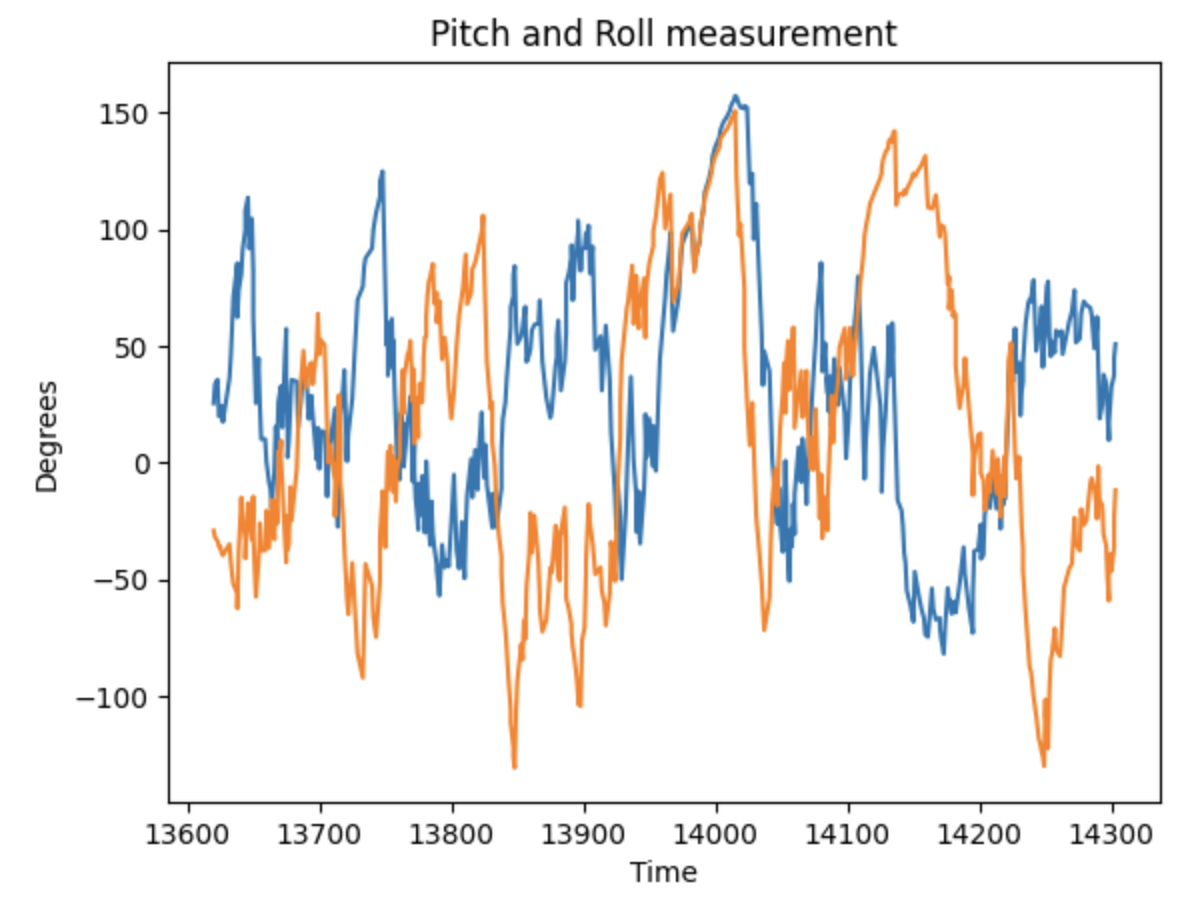
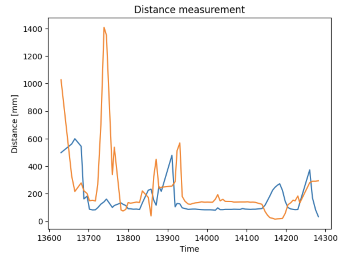
Finally, we taped the two ToF sensors, IMU and the Artemis onto the car and collected data over 5 seconds. Then, the data was sent over to the computer through bluetooth and plotted in python.
