Prelab
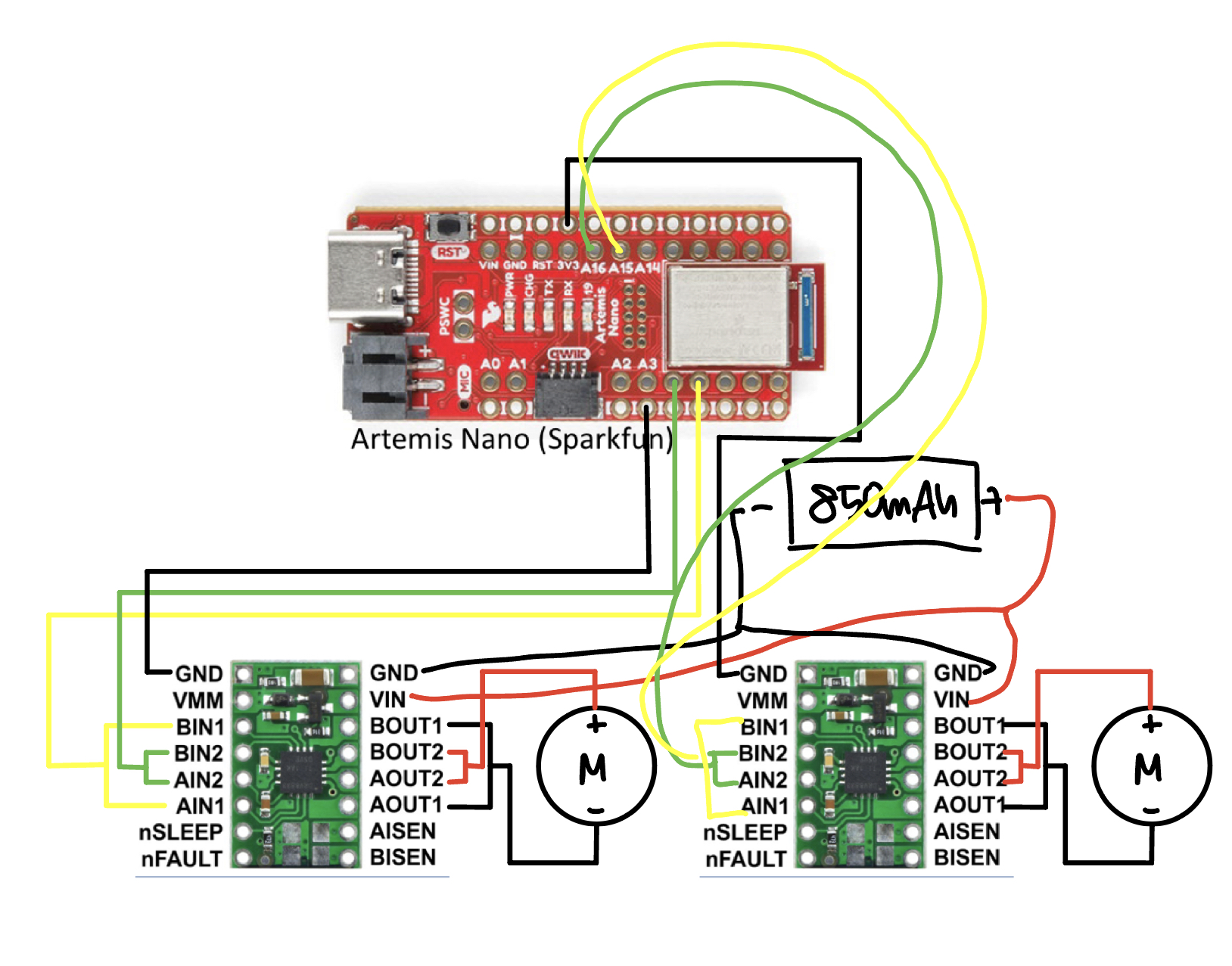
Before taking out the default control PCB and the motor connection, I drew the connection between the Artemis, motor controllers, motors and power beforehand. I decided to use pins 4, 5, 15, and 16 on the Artemis for PWM signals, and all the connections in the motor controller was parallel coupled in order to double the current for the motor drivers.
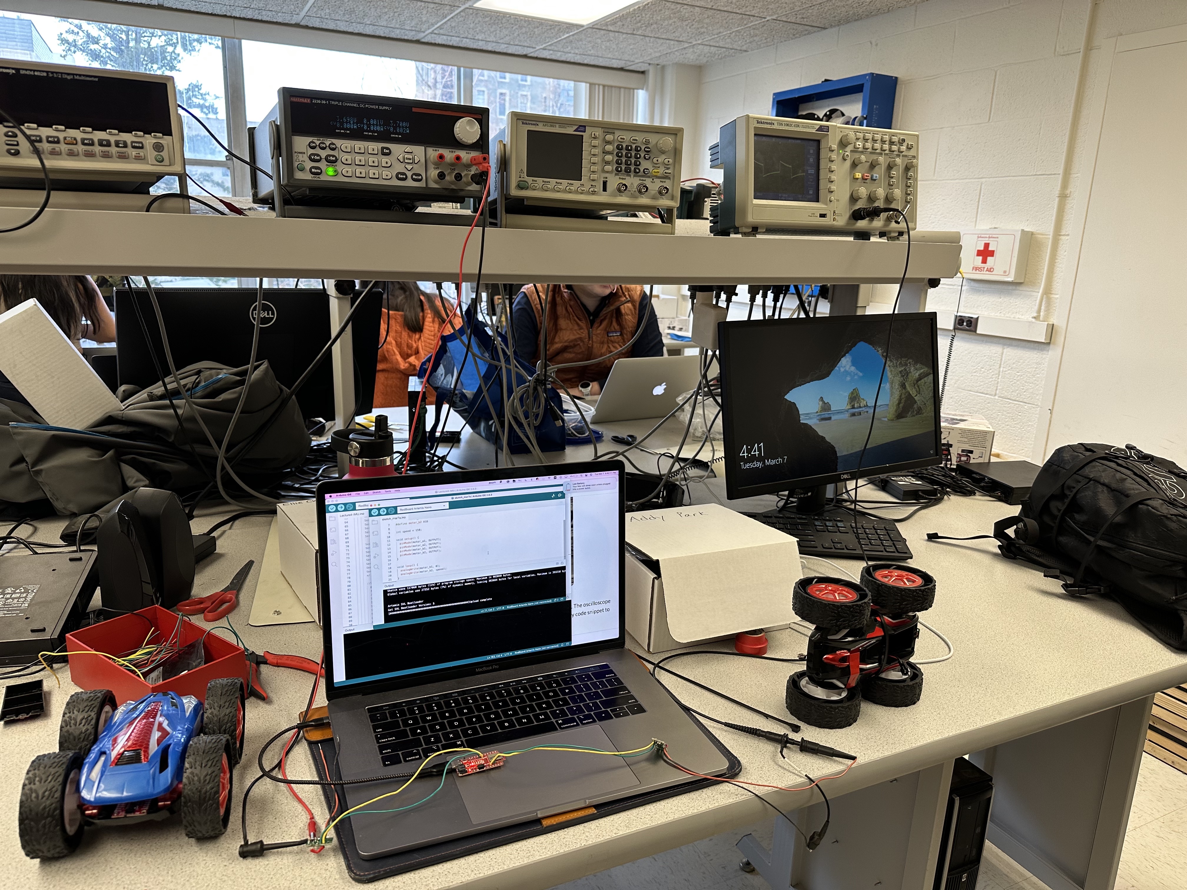
Power supply and Oscilloscope hookup
Before finalizing the wiring, I used the external power supply and the oscilloscope to verify my circuit. To replicate the motor batteries, I used 3.7 V as my voltage input for the motor driver and generated the PWM signal.
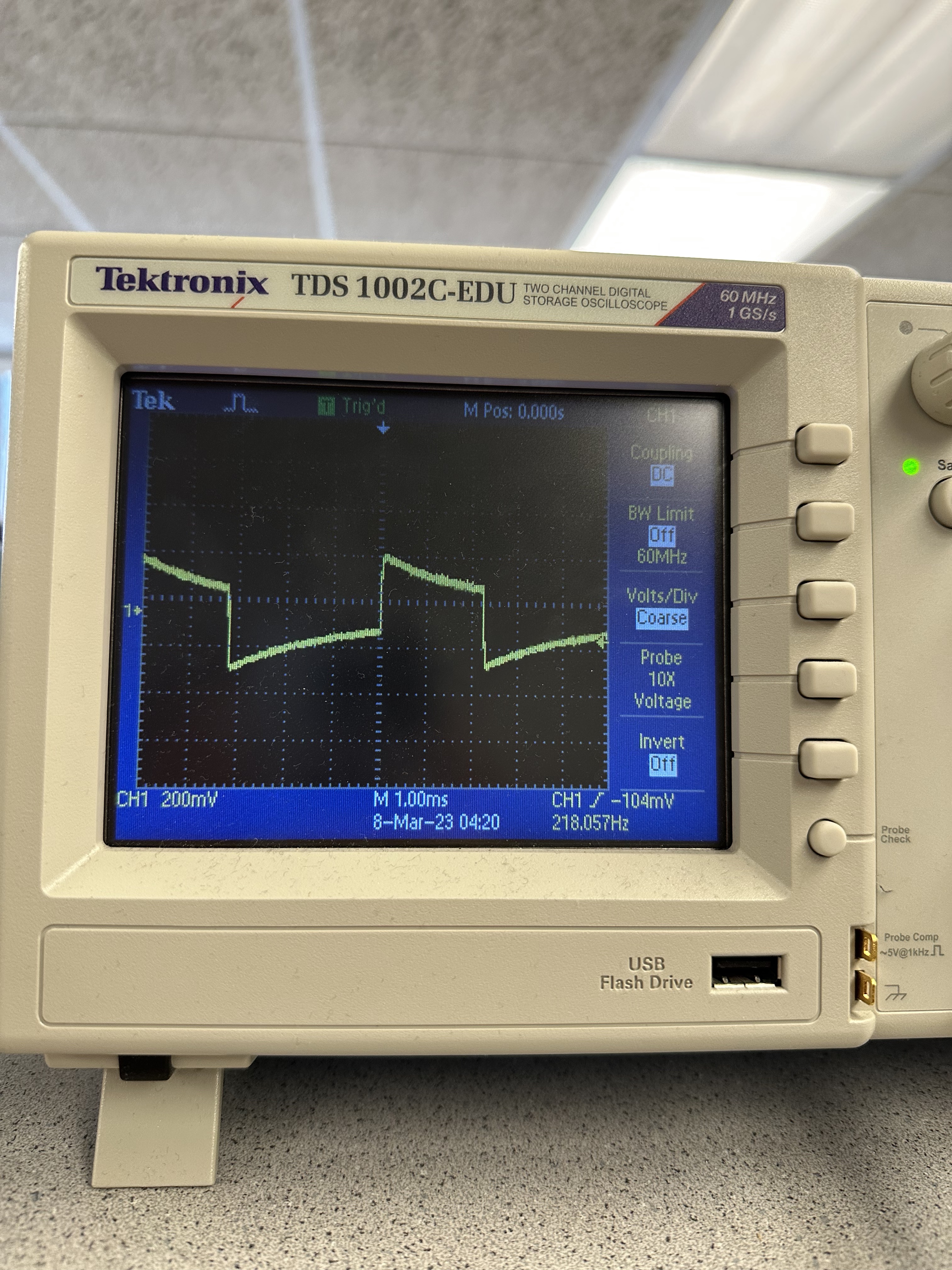
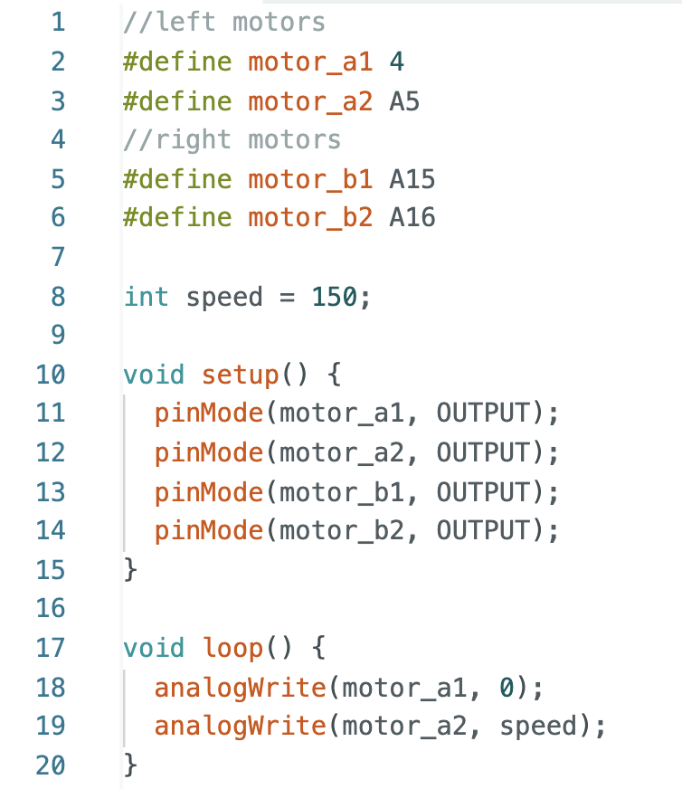
The image below is the PWM signal output on the oscilloscope, and the code snippet to generate the signal. I used analogWrite() command to generate the PWM signal fo 150 and the oscillosope result validates my circuitry.
Motor testing
Wheels alternatively spinning
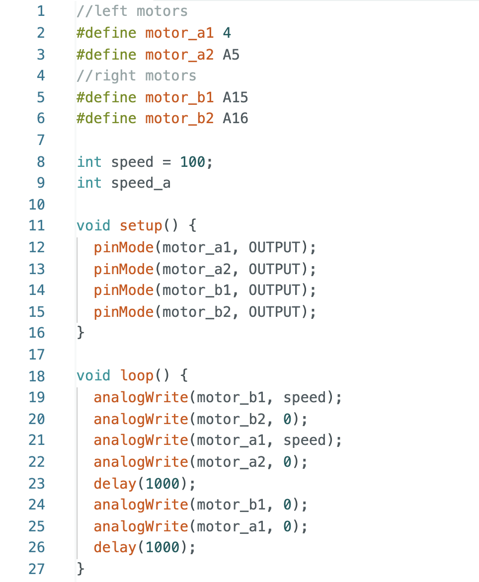
Both motors spinning fowards
Both motors spinning backwards
Car Assembly
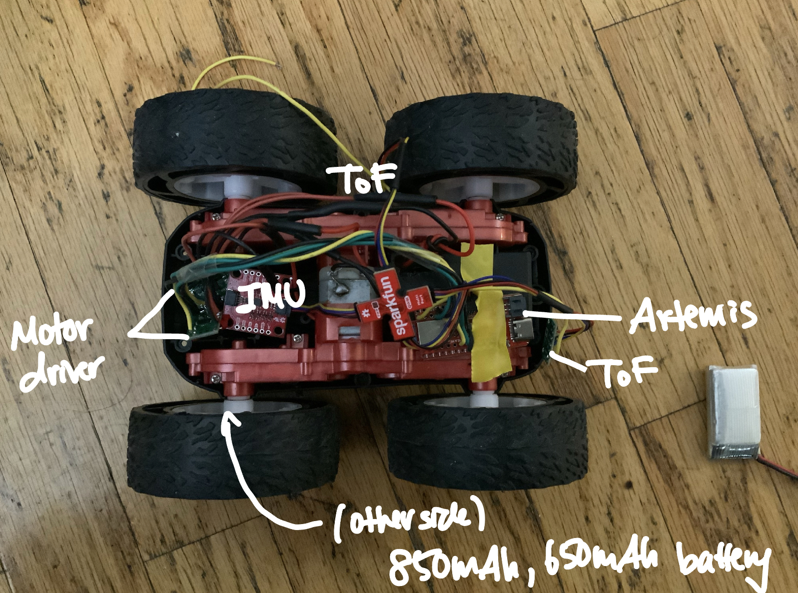
Below is an image of my car, with the Artemis, two ToF sensors, one IMU and two motor controllers all connected and organized. The battery for the motor controllers is on the other side of the car for organization and all cables will be tightened with cable ties for the 360 degrees stunts in the future labs. I purposely dispersed the sensors in order to spread out the weight for better maneuver ability.
Calibration
By slowing increasing the PWM value through analogWrite function, the lower bound of the PWM signal was found to be around 45.
As seen in the video below, my car was drifting to the left drastically when both motors had the same input. To ensure that the car moved fairly straight, I implemented a calibration factor so that the car moved approximately along the straight line.
This video shows the car movement after the calibration. It is moving fairly in a straight direction, unlike the video below. The code snippet is also attached, where the calibration for the right motor was 0.65 compared to the left motor.
Open Loop
The video below is my open loop demonstration, where I moved the robot straight, turned right, moved straight then moved backwards.